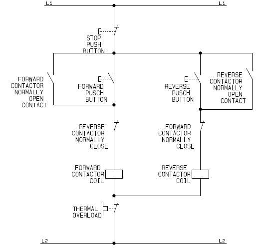
The electrical schematic diagram of a DOL electric motor control (ckt) circuit:
 |
| DOL forward reverse motor control circuit |
- Stop push button switch (Normally-Close Contact) - 1 piece
- Forward push button switch (Normally-Open Contact) - 1 piece
- Reverse push button switch (Normally-Open Contact) - 1 piece
- Magnetic contactor coils (for forward contactor and reverse contactor) - 2 units
- Forward contactor auxiliary contact (Normally-Open Contact) - 1 piece
- Forward contactor auxiliary contact (Normally-Close Contact) - 1 piece
- Reverse contactor auxiliary contact (Normally-Open Contact) - 1 piece
- Reverse contactor auxiliary contact (Normally-Close Contact) - 1 piece
- Thermal Overload Relay Contact - 1 piece
(Open in New Window)
Procedural sequence to learn about the method of operation of the DOL electric motor control (ckt) circuit:
- RUN MODE: Depending on the choice of the motor rotational direction, the operator presses the forward or the reverse push button switch. With the stop push button switch and the thermal overload contact remained close at OFF state, then power flows down to the selected forward or reverse main contactor coil.
- When any of the forward or the reverse contactor coil is energized, its auxiliary contact connected in parallel across the forward or the reverse push button switch closes which serves as a holding contact to maintain the forward or the reverse contactor coil energized after the operator releases his finger from any of the push button switches.
- STOP MODE: The operator presses the stop push button switch. This action disconnects the control circuit from the power source which prevents power flow to all energized contactor coils as a result of the opening of the normally-close contact of the OFF push button switch.
- CIRCUIT INTERRUPTION: The thermal overload relay detects motor overload current, which when detected will activate the thermal switch to open its normally-close contact to isolate power flow to all energized coils in the circuit, thus, deactivating the control (ckt) circuit.

